
- Test station: 1 station, measuring one sample at a time. Test piece size: length > 1200mm.
- Torch: Band-type propane gas torch with venturi mixer nozzle 500 mm nominal length
- Gas flow range: 0-50L/min adjustable
- Air flow range: 0-250 L/min adjustable
- Power supply voltage: AC380V±10%,50Hz three-phase five-wire
- Gas source: liquefied petroleum gas or propane, compressed air
- Flame temperature: 450°-950° degrees adjustable
- Sensing system: 2 stainless steel K-type thermocouples, can withstand temperature 1100 degrees
- Running power: 3KW
- Regulating range: AC60V~AC1100V
- Control test bench adopts PLC control, touch screen operation, convenient and intuitive.
- Gas flow meters: Mass flow controllers are used.
- Short-circuit method: The device changes the previous method of using fuses and adopts a new type of circuit breaker, which saves the cumbersome way of replacing fuses every time.
- The exhaust system is set up in the side of the chassis, which can effectively and quickly exhaust the waste gas, and can ensure the oxygen content in the chamber during the test, so that the test results will be more accurate.
- Continuous testing device: The test is conducted by allowing current to pass through all cores of the cable, with three single-phase transformers having sufficient capacity to maintain the maximum allowable leakage current at the test voltage. At the other end of the cable a lamp is connected to each core and a current close to 11A is loaded at the rated voltage of the cable. A signal is output when the specimen is shorted/broken during the test.
- The equipment has the following safety protection devices: power overload, short-circuit protection, control circuit overload protection.

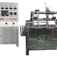
DLNH-1000A cable fire-resistant characteristic test device
Overview:
This machine is suitable for testing the fire resistance characteristics of mineral insulated cables and wires and cables with fire-resistant layers. This machine specifies the test device to be used for cables or fiber optic cables that are required to maintain the integrity of the line when individually supplied with a flame at a temperature of not less than 750°C (to control the output of heat) for the fire test.
Conformity standards: according to the requirements of national standards of flame retardant and fire-resistant cables GB/T19216-2008, GB/T19666-2019, MT/T386-2011, British Standard BS6387, BS8491, IEC60331-2009 and other standard requirements.
Related products
-
 Test and inspection equipment
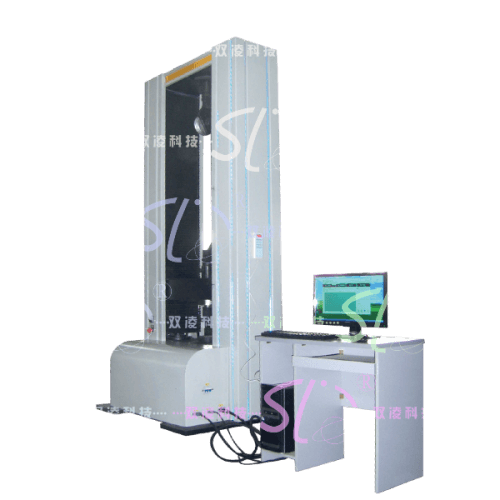
DL-30KN Wire Cord Core Conveyor Belt Core Rubber Tensile Tester
Read more -
SGM-02B型输送带智能滚筒摩擦试验机(水印)-500x500.png)
-
 Test and inspection equipment
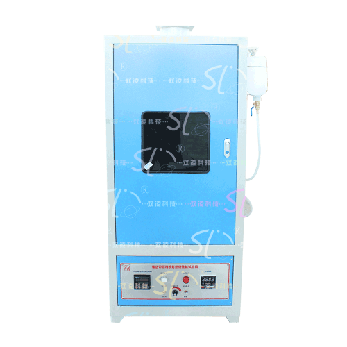
SJPR-01B Alcohol Torch Flame Retardant Performance Test Chamber for Wind Tubing Fabric Rubber Ring
Read more -
 Test and inspection equipment
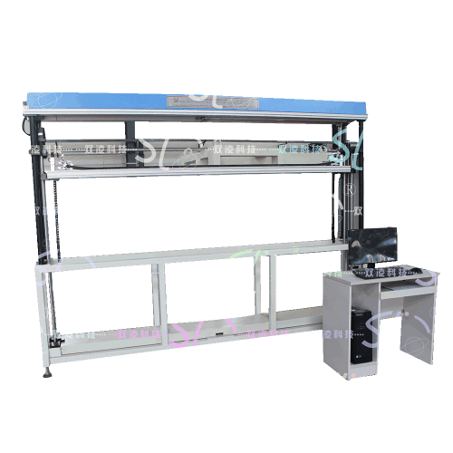
SC-2 Conveyor Belt Transverse Flexibility and Groove Formation Tester
Read more